Deferred Renderer with SSR
Deferred Rendering, Screen Space Reflections, OpenGL C++, OpenGL, Nsight Graphics
Deferred Rendering
Motivation
Forward rendering shades every fragment the rasterizer produces, even ones that get overwritten later by closer geometry. It also scales poorly with light count: the cost grows as O(objects × lights), because every object has to evaluate every light in its shader.
Deferred rendering decouples geometry from lighting. The first pass writes surface attributes into textures (the G-Buffer), and the second pass reads those textures and computes lighting once per screen pixel — regardless of how much geometry was behind it. This makes the lighting cost scale with screen resolution instead of scene complexity, and enables techniques that need access to neighboring pixel data (like SSR).
Geometry Pass & G-Buffer
The first pass renders the scene into multiple render targets simultaneously using MRT (Multiple Render Targets). No shading happens here — each fragment just writes its raw attributes to the appropriate buffer.
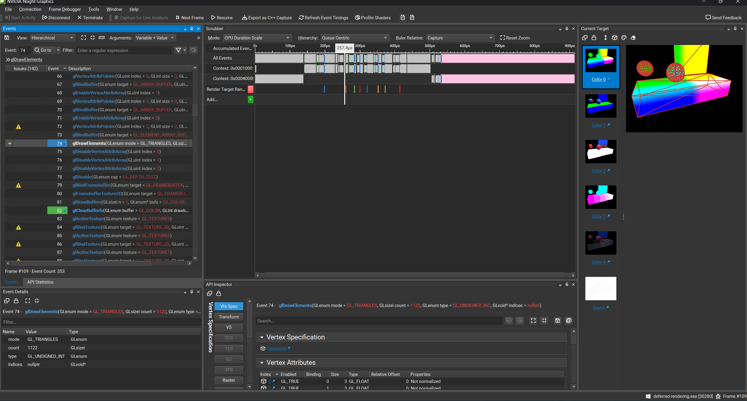
layout (location = 0) out vec4 gb_WorldSpacePosition;
layout (location = 1) out vec4 gb_Normal;
layout (location = 2) out vec4 gb_Albedo;
layout (location = 3) out vec4 gb_Metal_Rough_Mask;
The G-Buffer layout I used stores:
- World-space position — the starting point for reflection ray marching
- World-space normal — used to compute reflection directions and lighting
- Albedo — base surface color
- Metallic / Roughness / Mask — packed into a single RGBA texture. The mask channel flags whether a pixel contains geometry at all, so downstream passes can early-out on empty background pixels
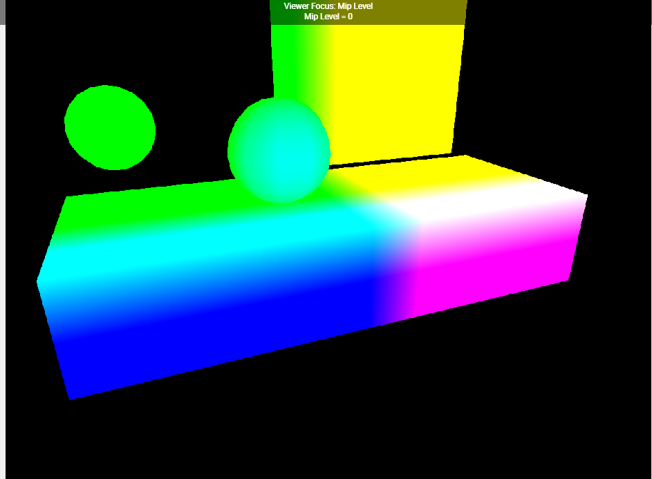
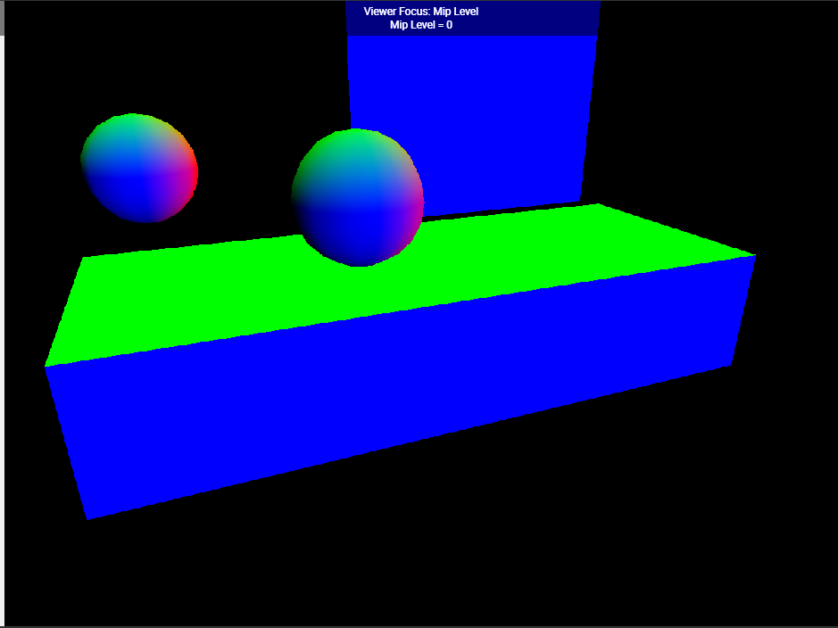
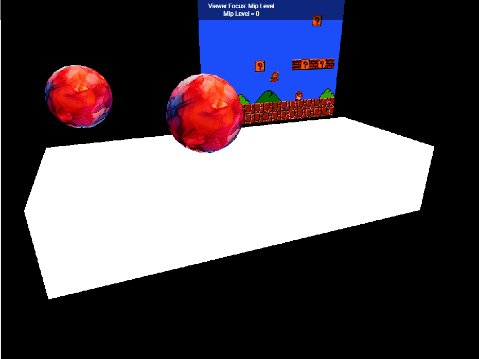
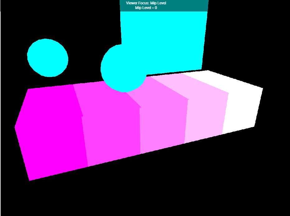
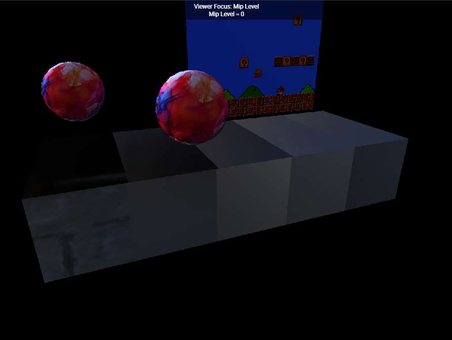
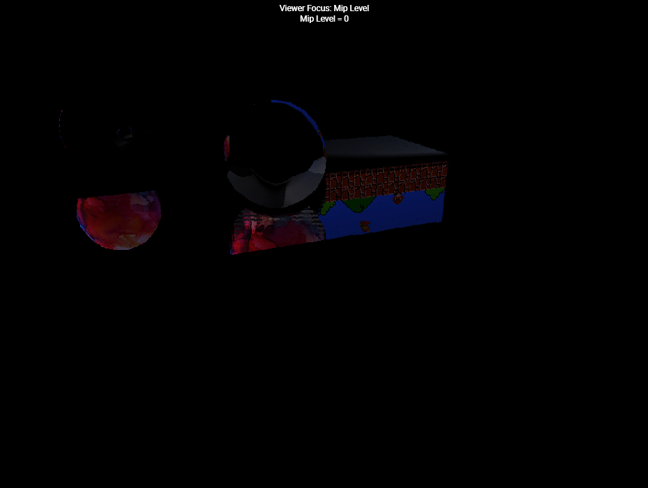
Because all of these are written in a single pass, the vertex shader only runs once per vertex regardless of how many attributes we need downstream.
Lighting Pass
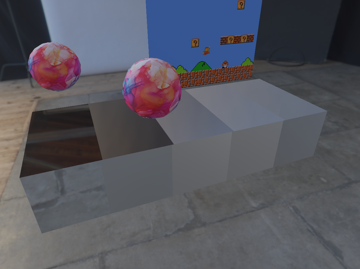
The second pass draws a single full-screen quad. The fragment shader runs once per screen pixel, samples the G-Buffer textures at the current fragment’s UV, reconstructs the surface properties, and computes lighting.
Because lighting now runs per visible pixel instead of per rasterized fragment, overdraw stops being a shading problem — it’s only a bandwidth problem for the G-Buffer writes. Adding more lights also becomes cheap, since each additional light is just another loop iteration inside the same full-screen pass.
1000 lights, 8 non-overlapping geometry


1000 lights, 125 overlapping geometry
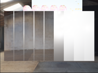


Image-based Lighting (Environment Maps)

Environment maps are considered to be infinitely far away, so every fragment in the scene is assumed that it’s placed exactly in the center of the map. This assumption simplifies light computation in various ways. As our shader model, we will be using the cook-torrance model that was implemented in Epic Games’ Unreal 4 Engine, and is used as the general ‘standard’ PBR shader in contemporary real-time applications.


Diffuse Convolution
The main difference between light sources with finite areas such as point lights or area lights and environment maps is that for environment maps, lights come in from all directions.
Since we assume that all points lie in the center of the environment map, we can assume that the same amount of radiance is coming into the pixel in all directions.
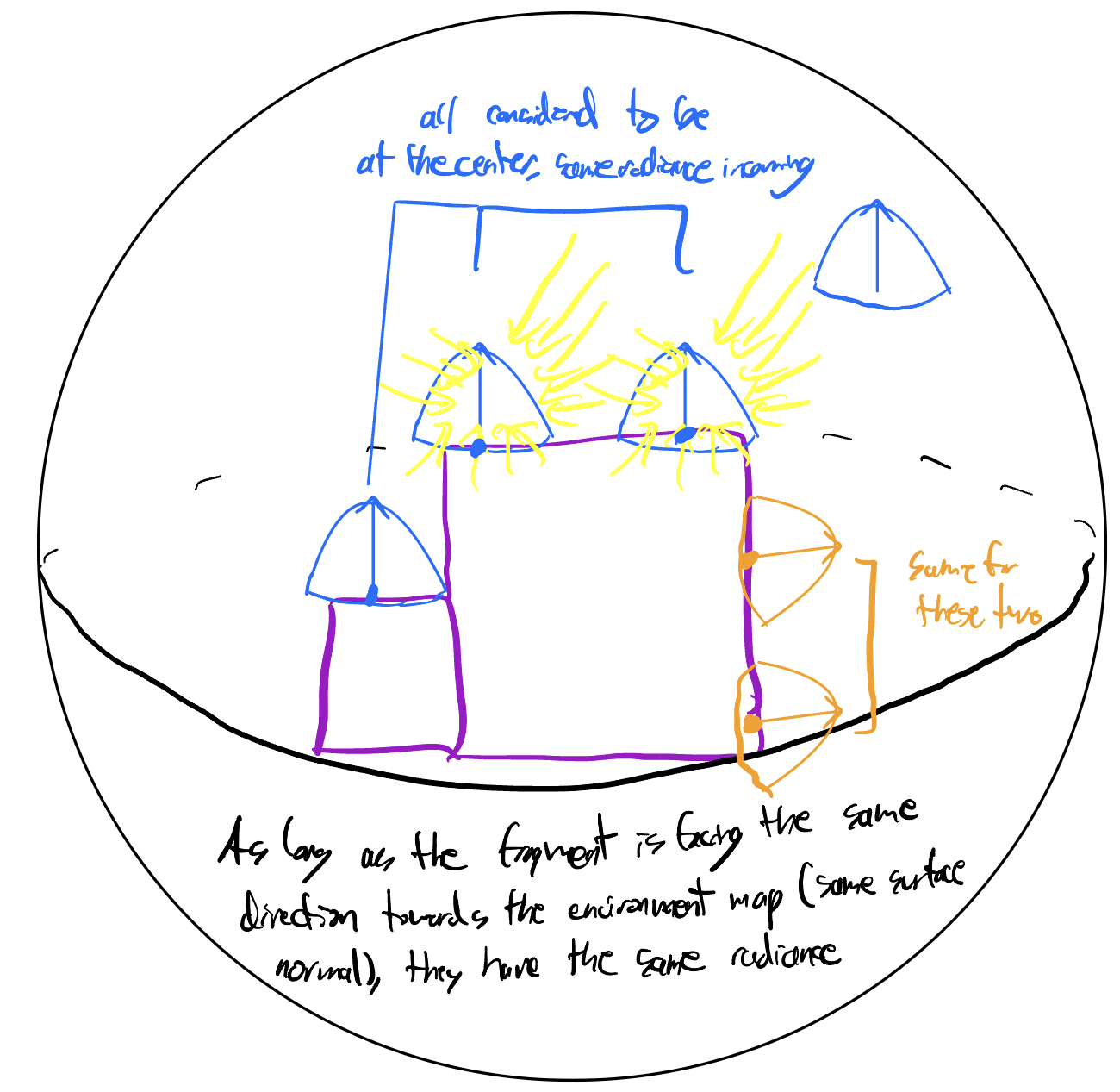

This means that as long as fragments are facing the same direction toward the environment map (same surface normal), the amount of light that they receive from the environment map is the same. Therefore, we can precompute how light reaches for every surface normal save it into a cubemap.

Glossy(Specular) Convolution
Precomputing the specular convolution map is a little trickier. First, we have to split the integral to as below.

The first part can be precomputed by random sampling near the surface’s normal along it’s brdf. However, the lower the pdf, we sample from higher mip maps to prevent unexpected high valued colors from producing fireflies.
The other part of the equation has us precompute the Fresnel coefficient of the Cook-Torrance microfacet BRDF.


Note that the Cook-Torrance BRDF’s DGF term is being divided by F, leaving only DG in the integrand. We’ve effectively rearranged the equation from the Fresnel term’s point of view — pulling F₀ outside the integral so what remains depends only on the viewing angle (N·V) and roughness. We can precompute these integral values using Monte Carlo estimation because the result no longer depends on the material’s base reflectance F₀ or the environment map — meaning a single 2D lookup table works for any material under any lighting.

The x-axis represents how tanget wo is to the susrface, and the y axis represents roughness. The red channel represents the Fresnel term’s scale, and the Green channel represents its bias.
Here are the performance comparisons for precomputed IBL and live IBL


Note that the precomputed IBL computed 4096 samples for convolution, while live IBL computed 32.
Should live IBL precompute 32, the program gets so slow it becomes unusable.

Screen Space Reflections
With the G-Buffer already holding position, normal, and color for every visible pixel, SSR becomes tractable: we can trace reflection rays through screen space itself, using the depth buffer as a cheap proxy for scene geometry.

For each fragment, I reflect the view direction around the surface normal to get a reflection ray, then march that ray in screen space. At each step, I compare the ray’s depth to the G-Buffer depth at that screen position — if the ray has gone behind a surface, we’ve hit geometry, and the pixel color at the intersection becomes the reflected color.
So basically we start off in world space by sampling the world space coordinates via the position gBuffer
World Space -> compute wi by reflecting wo from normal -> compute start and end of ray march in world using max_distance -> convert start and end position to Pixel Space (but store view space z coordinate of ray start and end) -> start marching along the pixel space -> for each march, use t to compute perspective correct interpolation to get the z coordinate in view space -> sample and compute View Space position of geometry located in the current pixel and compare with current ray’s z coordinate -> if the current ray’s z coordinate is smaller than the geometry’s z coordinate, geome” try detected, sample color using uv of current ray’s pixel location -> store in texture, with blended alpha values depending on position

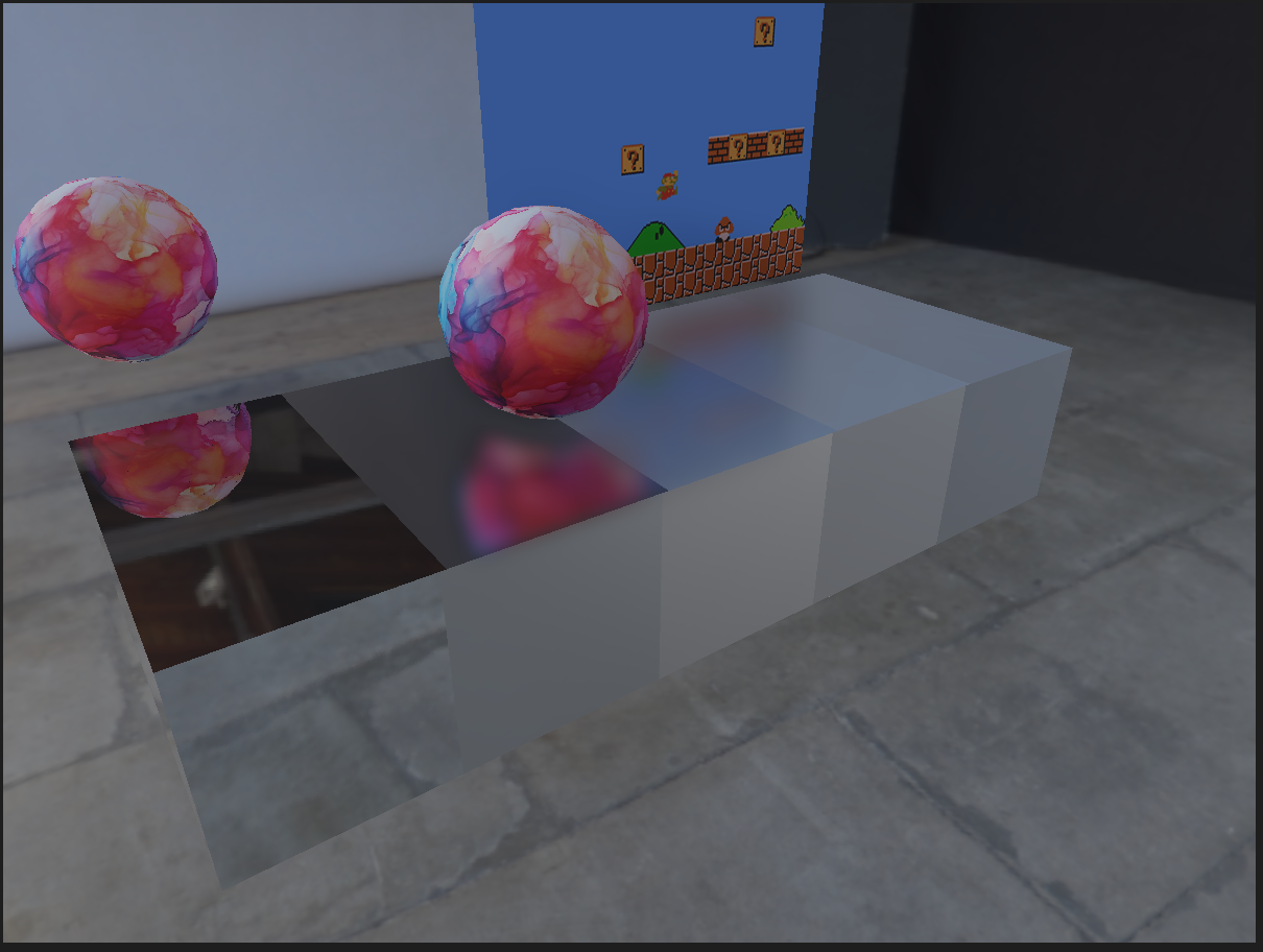
Result
References:
UPenn CIS 5610 Deferred Rendering Course Notes - Adam Mally
UPenn CIS 5610 Screen-Space Reflections Course Notes - Adam Mally
https://graphics.stanford.edu/papers/ravir_thesis/chapter4.pdf